

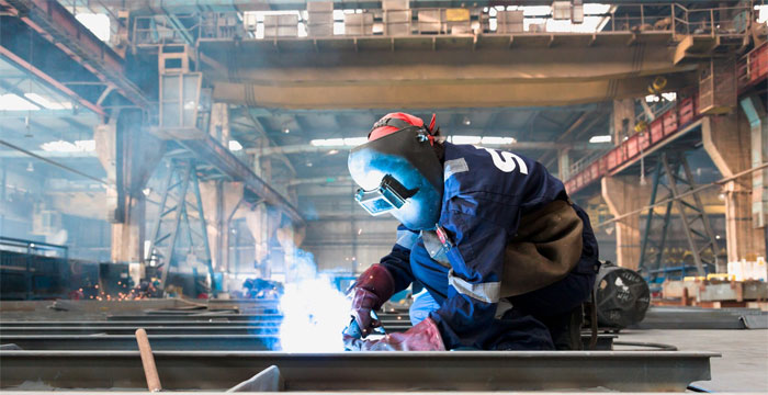
Welding is the primary joining technology for permanent structural assemblies across heavy infrastructure, pressure vessels, maritime hulls, pipelines, and aerospace frames. Unlike mechanical fasteners, which rely on localized shear or friction clamping forces, fusion welding melts the base materials together along their interface—often introducing a compatible filler metal—to form a continuous, monolithic metallic bond upon cooling. However, because welding introduces localized thermal energy into the joint, it functions as a microscopic casting process embedded within a wrought structural component.
Ensuring the long-term structural integrity of a welded joint requires managing metallurgical phase transformations, thermal stress accumulation, defect formation, joint design physics, and rigorous non-destructive evaluation (NDE) protocols.
1. Physical Metallurgy of the Fusion Weldment
A completed fusion weld is not a single uniform material. Instead, it comprises three distinct metallurgical zones, each featuring unique grain structures, mechanical strengths, and chemical properties:
CROSS-SECTIONAL ZONES OF A FUSION WELDMENT
+——————–+——————–+——————–+
| Base Metal (BM) | Heat-Affected Zone | Weld Metal (WM) |
| | (HAZ) | |
+——————–+——————–+——————–+
| Parent plate metal | Solid-state phase | Solidified liquid |
| Unaltered grain | shift; coarse and | mixture of base |
| structure | fine-grain regions | & filler metals |
+——————–+——————–+——————–+
1. The Weld Metal (WM) Zone
The central zone where base metals and filler materials melt, intermix, and solidify. As this molten pool cools, metal grains nucleate at the cooler un-melted solid boundaries and grow inward toward the centerline, forming elongated, directional columnar grains. The mechanical properties of the weld metal depend directly on the alloy composition of the filler wire, cooling rates, and shield-gas protection against atmospheric contamination.
2. The Heat-Affected Zone (HAZ)
The region of parent metal immediately adjacent to the fusion boundary. Although the HAZ does not melt, the intense thermal cycle drives solid-state metallurgical phase transformations and grain growth:
- Coarse-Grained HAZ (CGHAZ): Located directly along the fusion line, where temperatures approach the melting point. High heat drives rapid grain growth, resulting in large, coarse grains that exhibit low impact toughness and high crack susceptibility.
- Fine-Grained HAZ (FGHAZ): Positioned further from the fusion boundary, where temperatures barely exceed the upper critical transformation point. The lower peak temperature induces grain refinement (recrystallization), producing a fine-grained structure with high yield strength and impact resistance.
3. The Unaffected Base Metal (BM)
The surrounding parent plate material that experiences peak temperatures insufficient to alter its microstructures, mechanical strength, or physical properties.
2. Hydrogen-Assisted Cold Cracking and Thermal Preheat Dynamics
One of the most dangerous structural failure mechanisms in structural steel welding is Hydrogen-Assisted Cold Cracking (HACC), also known as delayed cracking or underbead cracking. HACC typically occurs hours or days after the weld has cooled to ambient room temperature, making it a critical threat to field-erected structures.
The Three Conditions for HACC
Cold cracking occurs when three factors converge simultaneously:
- Diffusible Hydrogen: Atomic hydrogen dissolves into the liquid weld pool from moisture on the plate, damp flux coatings, or oil and grease contamination. As the metal cools, the solubility of hydrogen drops, forcing hydrogen atoms to diffuse into the solid grain boundaries of the HAZ.
- Susceptible Microstructure: High-carbon and high-alloy steels undergo rapid cooling, transforming the HAZ into a hard, brittle martensitic grain phase.
- High Tensile Residual Stress: The natural shrinkage forces of the cooling weld bead apply intense mechanical tension across the joint.
HYDROGEN-ASSISTED COLD CRACKING (HACC) TRIAD
Diffusible Hydrogen
/\
/ \
/ \
/ \
/ \
Susceptible Microstructure —- Tensile Residual Stress
Mitigation via Preheat and Interpass Temperature Control
To prevent HACC, structural codes (such as AWS D1.1 and ASME Section IX) mandate strict preheat protocols:
- Preheating: Flame or electrical induction heating warms the base plates to a specific temperature (typically between 100°C and 250°C) prior to welding. Preheating slows the overall cooling rate, giving dissolved hydrogen ample time to diffuse safely out of the steel before the metal drops below 100°C. Furthermore, a slower cooling rate prevents the formation of brittle martensite, favoring softer, ductile ferrite-pearlite grain structures.
- Interpass Temperature Maintenance: Ensures that multi-pass welds do not drop below the minimum preheat temperature between successive passes, preventing localized quenching effects.
3. Structural Joint Design and Load Path Dynamics
Selecting and designing the correct weld joint configuration dictates how efficiently applied mechanical loads pass through an assembly. The primary welded joint geometries fall into two core classifications:
PRIMARY STRUCTURAL WELD JOINT GEOMETRIES
1. FILLET WELD 2. GROOVE WELD
(Corner / T-Joint) (Butt Joint)
| Member A | Member A |
| | |
+–+=== ===+==========+===
| | / (Weld Throat) | | Weld | |
+–+–/ +–+———-+–+
| Member B | | Member B |
Fillet Welds
Fillet welds join two overlapping or perpendicular metal surfaces (such as T-joints, lap joints, and corner joints) without full edge preparation. The load-bearing capacity of a fillet weld is determined by its Effective Throat Thickness—the shortest distance from the root of the weld to its face.
While fillet welds are fast and cost-effective to produce, they introduce abrupt directional changes in the structural load path. This geometry concentrates stress along the toe and root of the weld, making fillet joints susceptible to fatigue failure under dynamic or cyclic loading.
Groove Welds (Butt Joints)
Groove welds join two plates lying within the same plane. To achieve structural integrity, the plate edges are bevelled to form V, U, or J grooves that accommodate multiple passes of filler metal:
- Partial Joint Penetration (PJP): The weld metal penetrates only a portion of the total plate thickness, leaving an unfused root region. PJP welds are acceptable for static, low-stress applications.
- Complete Joint Penetration (CJP): The weld metal penetrates fully through the entire thickness of the joint, completely fusing both plates into a continuous structural cross-section. CJP groove welds eliminate internal stress concentrators, providing superior resistance to fatigue, impact, and reversal loads.
4. Solidification Defects and Discontinuities
During the transition from liquid to solid, welds can develop structural defects that compromise joint capacity. Weld quality protocols distinguish between minor discontinuities (acceptable irregularities within code limits) and structural defects (unacceptable flaws requiring excavation and repair).
| Defect Type | Physical Description | Primary Root Causes | Preventative Actions |
| Porosity | Spherical voids or gas pockets trapped inside the solidifying weld metal. | Atmospheric contamination, loss of shield gas, moisture on base plates, or dirty filler wire. | Clean joint surfaces, restore shielding gas coverage, and use dry low-hydrogen electrodes. |
| Lack of Fusion (LOF) | Incomplete adhesion between the weld metal and the base plate sidewalls or adjacent passes. | Low heat input, fast travel speed, incorrect torch angle, or heavy mill scale on plate edges. | Boost welding amperage, reduce travel speed, optimize torch manipulation, and grind plate scale. |
| Incomplete Penetration | Weld metal fails to extend fully through the root of a full-penetration groove joint. | Root opening too narrow, root face too thick, misalignment, or low welding current. | Adjust joint fit-up geometry, increase root gap, and use proper back-gouging techniques. |
| Undercut | A groove or channel melted into the base metal along the weld toe that is left unfilled. | Excessively high welding voltage, fast travel speed, or improper torch positioning. | Lower welding voltage, slow travel speed, and adjust torch angle to dwell briefly at the edges. |
| Hot Cracking (Solidification) | Centerline longitudinal cracks occurring at elevated temperatures as the weld freezes. | High sulfur/phosphorus impurities, poor width-to-depth weld bead ratios, or high joint restraint. | Select low-impurity filler materials, adjust bead geometry to be wider than deep, and lower restraint. |
5. Weld Quality Evaluation and Non-Destructive Testing (NDT)
Validating that a completed weldment meets code requirements requires systematically applying destructive and non-destructive testing (NDT) methodologies.
+———————————–+
| WELD TESTING METHODOLOGY |
+—————–+—————–+
|
+—————————+—————————+
| |
+—–+—–+ +—–+—–+
| Surface / Subsurface NDT | | Volumetric NDT |
+———–+ +———–+
• Visual Inspection (VT) • Ultrasonic Testing (UT)
• Magnetic Particle (MT) • Radiographic Testing (RT)
• Liquid Penetrant (PT) • Phased Array UT (PAUT)
Surface Inspection Methods
- Visual Inspection (VT): The foundational inspection method. Certified Welding Inspectors (CWIs) use specialized gauges to measure fillet weld leg size, throat thickness, edge alignment, surface profile, undercut depth, and weld reinforcement height.
- Magnetic Particle Testing (MT): Applied to ferromagnetic materials. A magnetic yoke induces a magnetic field through the weld joint while fine iron particles are dusted over the surface. Discontinuities interrupt the magnetic flux lines, causing particles to cluster along the edges of micro-cracks or surface-breaking flaws.
- Liquid Dye Penetrant Testing (PT): A bright visible or fluorescent dye is applied to non-porous surfaces. Capillary action draws the dye into narrow surface-breaking cracks. After washing away surface dye, a developer draws the trapped dye back out, revealing clear surface indications.
Volumetric Inspection Methods
- Radiographic Testing (RT): X-ray or gamma-ray radiation passes through the weld joint onto film or digital detector arrays. Variations in density produce a permanent visual radiograph. Internal voids, slag inclusions, or incomplete penetration appear as darker regions due to lower radiation absorption.
- Ultrasonic Testing (UT) and Phased Array UT (PAUT): High-frequency sound waves travel through the metal. Internal flaws, void walls, or sidewall fusion defects reflect sound waves back to a receiving transducer. Advanced Phased Array UT uses multi-element transducers to sweep sound beams across multiple angles, generating real-time cross-sectional images of the internal weld geometry without radiation safety hazards.
6. Welding Procedure Specifications (WPS) and Qualification
To eliminate guesswork on the shop floor, code-compliant welding operates under a standardized quality control system based on three core documents:
- Procedure Qualification Record (PQR): A historical record documenting the welding parameters used to fabricate a test coupon, alongside the destructive laboratory test results (tensile tests, bend tests, and Charpy V-notch impact tests) required to prove the joint’s mechanical properties.
- Welding Procedure Specification (WPS): The certified instruction sheet issued to shop welders. The WPS dictates explicit boundaries for essential variables, including material grade, process type, joint design, filler wire classification, shielding gas mixture, voltage, amperage, travel speed, preheat, and interpass limits.
- Welder Performance Qualification (WPQ): A certificate verifying that an individual welder possesses the physical skill to produce sound welds compliant with a specific WPS in defined positions (flat, horizontal, vertical, or overhead).
Stainless steel pipes kampala uganda